DeckWise® Pedestals
DeckWise® Adjustable Screw-Jack Pedestals Self-Leveling Deck Tile System
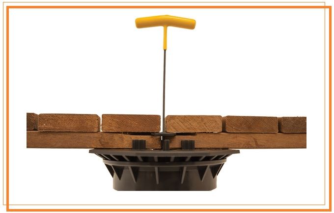
Our DeckWise®, Altitudes Pedestal™ System24" x 24" Hardwood Deck Tile Elevating System has been developed to level underutilized roof tops, plazas, and balconies into beautiful spaces when used with our Brazilian Hardwood Roof Tiles. These Pedestals elevate our 24" x 24" hardwood roof deck tiles over multiple roof top slopes to create a smooth and level deck surface.
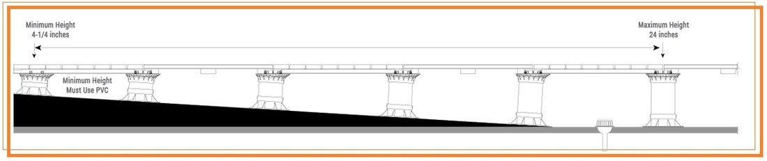
Each pedestal has the ability to be set from 4-5/32" at the lowest (this includes a short PVC pipe) up to 24" at their maximum safe height. The self-leveling swivel head has slope compensation from 0 - 5%. Our precise 3/16 inch spacer tabs are integrated into the head to produce the perfect tile gap spacing and are easily punched out for deck tile placements where tabs are not needed (such as around corners or around circumferences for added support). Additional pedestals are needed when supporting heavy objects such as planters, grills, Ipe Furniture, etc.
The Altitudes Pedestal™ system is compatible with WiseTile™ Hardwood Deck Tiles.
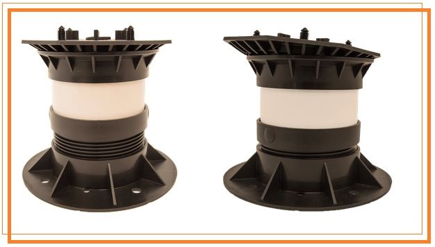
Screw-to-Adjust Base Height
The screw-to-adjust base height setting makes the final adjustment levels effortless for a perfectly level deck tile surface. The Altitudes Pedestal™ System head and base have deck drainage holes for water and are exceptionally stable with 4" PVC Schedule 40 Plain End Pipe. They are impervious to freeze/thaw cycles due to the use of 20% Talc added to a polypropylene resin.
Pedestals are warranted up to 1,200 lbs. of load.
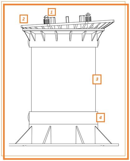
Adjustable Screw-Jack Pedestal
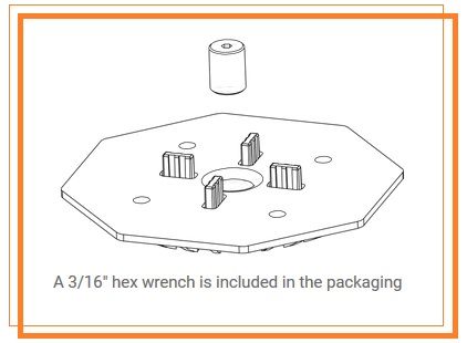
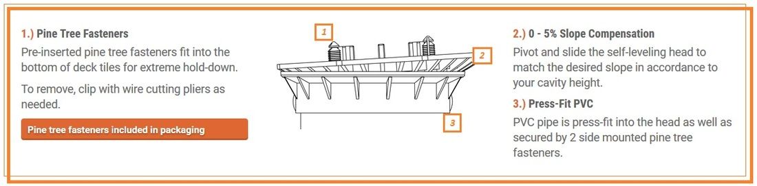
1.) Has 3/16" Spacer Tabs (4). To remove tabs: strike with hammer to punch them into the head cavity.
2.) Leveling Head comes pre-assembled. Loosen the stainless steel insert with a 3/16" hex wrench prior to installation. Tighten the insert during your initial leveling and for final height adjusting.
3.) 4" PVC - Schedule 40 Plain End Pipe After determining level deck tile cavity height, cut Schedule 40 PVC on site to fit your project. PVC is press-fit into the head and the base.
DO NOT USE OPEN-CELL PVC!
Drill 23/64" holes through the PVC at the designated holes in the head and base to insert pine tree fasteners.
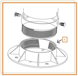
4.) Screw-Jack Base (screw-to-adjust base) comes with the coupling fully seated. Prior to your installation, turn the coupling out 1 full turn for fine adjustments (approx. 1/8" of the threads will show).
DO NOT extend more than 4 full turns!
Self-Leveling Slope Compensating Head
Screw-Jack Adjustable Base
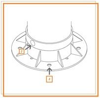
1.) Screw-To-Adjust - Adjust base height up or down for minute fractional increments with the threaded base for perfectly straight and level deck.
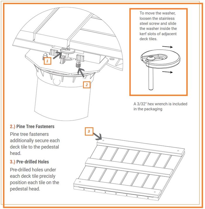
2.) Pine Tree Fasteners - Pine tree fasteners accompany all orders for secured the base and head to the PVC. Drill 23/64" holes into the PVC to insert the pine tree fasteners.
3.) Secure the Base - When applicable, fastening hardware can be used to secure the base to substrate.
Cutting Schedule 40 PVC Pipe
Cutting 4" PVC Schedule 40 Plain End Pipe to Size
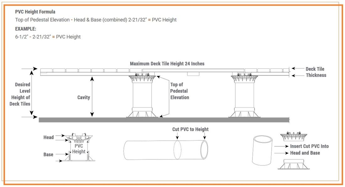
The PVC pipe fits inside the cavity of the pedestal head and the pedestal base. To acquire the correct height for your PVC, the head base and the nominal thickness of the deck tile must be subtracted from the finished elevation of the deck tile surface for accuracy. The screw-to-adjust base will provide for your final height adjustments.
The PVC 'press fit' connection of the head and bottom screw-jack base does not require gluing.
NOTE: The minimum height allowed for Altitudes Pedestals™ is 4-5/32 inches high. Minimum height pedestals must include 1-1/2" Schedule 40 PVC to connect the head and base.
Locking Deck Tiles Together
1.) Lockit Down Washer™
Your deck tiles are secured to the pedestal with pine tree fasteners (rated up to 166 lbs. of wind hold-down strength) and our patented adjustable Lockit Down Washer™. The washer fits into the corner kerf cut slots of deck tiles which, in turn lock and hold down your deck tiles to the pedestal head.
Insert the Lockit Down Washer™ into the corner kerf cut slot of all 4 hardwood deck tiles where they meet on a pedestal. First, slide a washer into 2 tile kerf corner slots and hand thread the 3/32" stainless steel screw into the stainless steel insert of the pedestal head. Install a 3rd deck tile by sliding
the washer out of the way and place over the pine tree fastener. Then install the 4th deck tile onto the pedestal's 4th corner in the same manner. Once all 4 deck tiles are in place and levelness is checked, center the washer and securely tighten the screw for maximum hold-down.
To remove a deck tile: loosen the stainless steel screw and slide the washer to the side into adjoining deck tiles and out of the way. All 4 corners of the deck tile that is to be removed, will need to have the washer loosened and slid to the side for deck tile removal.
Slope Compensation
Fixed Height or Slopes
Pedestals can be either a fixed height or adjustable for slope compensation. 0-5% slopes are easily managed by positioning the self-leveling head at the desired angle in accordance to the overall deck tile height needed.
Perimeter Containment, Parapets, Blocking, and Retention Walls
Any intended installation area of our pedestal hardwood deck tile system must fit tight inside the walls of the installation cavity and be restrained and contained. Roof tops must have parapet retaining walls, concrete dividers or other structural perimeter restraint capable of resisting lateral forces including seismic and wind. Blocking must be installed where deck tiles change heights such as stepping up or down. Deck tiles and pedestals will move if all sides are not tightly fit.
- 1% slope = .120 inches per foot drop
- 2% slope = .240 inches per foot drop
- 3% slope = .360 inches per foot drop
- 4% slope = .480 inches per foot drop
- 5% slope = .600 inches per foot drop
Perimeter "structural" framing and edging boards located at the outside of the deck tile perimeter must also be installed to provide restraint. No movement greater than one spacer tab should be allowed at the perimeter of the deck pedestal system. Cumulative movement in excess of 3/16 of an inch will void the Altitudes Pedestal™ System Limited Warranty.
Always seek the professional advice of a licensed and accredited architect prior to installation. MAKE SURE YOU ADHERE TO ALL LOCAL AND STATE BUILDING CODES FOR YOUR LOCATION.
Installation Process
Substrate Surface
The substrate surface which will receive the deck tile pedestal system must be clean and free of any projections and debris. It must be compact and structurally capable of carrying the live and dead load projected which, if not, may impair the performance of the pedestal system. The use of protection board, insulation and waterproof membrane must meet or exceed your local building codes.
Installing Deck Tiles & Pedestals
Prior to installation, verify all cavity elevations, desired pedestal heights and overall installation dimensions. Inspect the roof top substrate to confirm that it has been correctly prepared. If roof top preparation is the responsibility of others, notify the construction designer, contractor and architect in writing. Any deviations from the manufacturer's recommended installation guidelines will void your warranty or create an unsafe surface area. Attention to, and inspection of hardwood deck tiles and pedestals must be completed prior to installation.
Review of the deck tile pattern, layout grid, threshold starting point, and finished elevation should be shown on a plan view architectural drawing. Plans, CAD drawings and/or illustrations should be prepared and approved by an accredited architect or construction designer. Owner approval and sign-off of plans should be in writing and documented. Install deck tiles and pedestals in accordance with Altitudes Pedestal™ Systems and any other product manufacturer's guidelines. Installation requirements will vary for every individual job site.
Special Considerations & Tips for Safe Installations
Planters, grills and heavy objects must have 6 pedestals underneath each deck tile for additional support. Add a pedestal to the sides of all deck tiles that will receive additional weight.
- *Pedestal bases may be trimmed for a tight fit around a corner. DO NOT cut or trim the pedestal head.
- *Conduit and services running inside the cavity below can be easily accessed by removing 1 or more tiles.
- *Cut tiles to fit around conduit; use stainless steel screws from the underside to secure wood slats.
- *Notch cut tile corners to fit around conduit where needed.
- *Use construction adhesive to secure spacer tabs between tiles when not attached to the pedestal.
- *Tiles must fit snug around the perimeter with no movement allowed greater than 1 tab width.
- *Fill perimeter spaces with a section of tile to assure a tight fit; use construction adhesive for additional hold.
- *On small tile pieces/sections around the perimeter or a radius use construction adhesive on the pedestal for additional support.
- *Bottom leveling shims are not necessary.
Always seek the professional advice of a licensed and accredited architect prior to installation. MAKE SURE YOU ADHERE TO ALL LOCAL AND STATE BUILDING CODES FOR YOUR LOCATION.
Maximum Pedestal Load
1,200 lbs. Maximum Load (maximum per pedestal)
Safety value for maximum permissible load of 1,200 lbs. per pedestal shall not be exceeded. Specific usage is intended for pedestrian terrace roofs, plazas and technical floors. The various components of the DeckWise® Altitudes Pedestal™ System are manufactured from polypropylene resin charged with talc 20%.
Pedestals are warranted up to 1,200 lbs. of load. Please see complete Limited Liability Warranty for details at www.DeckWise.com/warranty
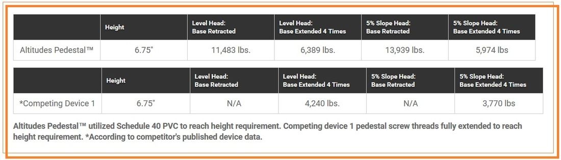
Pedestal Load Testing & Comparisons
The DeckWise® Altitudes Pedestals™ have been tested by an independent laboratory. Four tests were run using three samples per test with a zero slope and a 5% slope. A hydraulic press capable of generating 55 tons of downward pressure was used for testing. A 50 Kip MOREHOUSE load cell in combination with a Fluke data acquisition unit was used to record the loading of the sample. Samples were set in the press and loaded until failure.